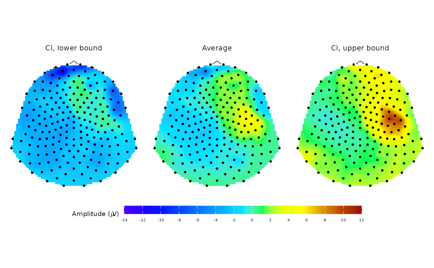
Plot topographic map of average EEG signal
plot_topo_mean.RdPlot a topographic circle or polygon map of the average EEG signal amplitude and its lower and upper confidence interval bounds using topographic colour scale.
The thin-plate spline interpolation model \(\text{IM:}\; \mathbb{R}^2 \rightarrow \mathbb{R}\) is used for signal interpolation between the sensor locations.
The output in the form of a ggplot object allows to easily edit the result image properties.
Usage
plot_topo_mean(
  data,
  mesh,
  coords = NULL,
  template = NULL,
  col_range = NULL,
  col_scale = NULL,
  contour = FALSE,
  show_legend = TRUE,
  label_sensors = FALSE
)
Arguments
- data
A data frame, tibble or a database table with input data to plot. It should be an output from
compute_meanfunction or an object with the same structure, containing columns:sensorwith sensor labels andaverage,ci_low,ci_upwith values of average signal and its lower and upper CI bounds in one time point (or precomputed average of multiple time points).- mesh
A
"mesh"object (or a named list with the same structure) containing at least aD2element with x and y coordinates of a point mesh used for computing the IM model, and atemplateelement specifying the sensor montage. If not defined, the point mesh with default settings frompoint_meshfunction is used.- coords
Sensor coordinates as a tibble or data frame with named
x,yandsensorcolumns. Thesensorlabels must match the labels in sensor column indata. If not defined, the template specified inmesh$template(or the default"HCGSN256") is used.- template
The kind of sensor template montage used. Available options are
"HCGSN256","biosemi128","biosemi256", and"system1005". Default setting is"HCGSN256".- col_range
A vector with minimum and maximum value of the amplitude used in the colour palette for plotting. If not defined, the range of input data (average and CI bounds) is used.
- col_scale
Optionally, a colour scale to be utilised for plotting. It should be a list with
colorsandbreakscomponents (usually created viacreate_scale). If not defined, it is computed fromcol_range.- contour
Logical. Indicates, whether contours should be plotted in the graph. Default value is
FALSE.- show_legend
Logical. Indicates, whether legend should be displayed below the graph. Default value is
TRUE.- label_sensors
A logical value indicating whether the sensor labels should also be plotted. Default value is
FALSE.
Value
A ggplot object showing the static topographic map of the signal divided into three panels: CI lower, mean, CI upper.
Additionally, the returned object carries a "diegr_metadata" attribute with metadata such as details about the mesh used for plotting.
Details
The spline interpolation is done independently for each CI bound and average.
Notes: If a mesh object is provided, its internal template name (mesh$template) overrides the template argument to ensure spatial consistency.
When custom coords are provided, they are always used for plotting the sensor locations. The template parameter (or mesh$template) is then used only for generating the background mesh if it is not provided.
See also
topo_plot, compute_mean, animated version: animate_topo_mean
Examples
# Plot average topographic map with CI bounds of signal for subject 2 from the time point 10
# (the time of the stimulus) excluding outlier epochs 14 and 15

# a) preparing data
# a1) extract required data
edata <- pick_data(epochdata, subject_rg = 2, epoch_rg = 1:13, time_rg = 1:10)
# a2) baseline correction (needed for suitable topographic map)
data_base <- baseline_correction(edata, baseline_range = 1:9)
# a3) average computing
data_mean <- data_base |>
dplyr::filter(time == 10) |>
compute_mean(amplitude = "signal_base", type = "jack", domain = "space")
# a4) prepare a mesh for plotting
M <- point_mesh(dimension = 2, n = 3000, template = "HCGSN256",
sensor_select = unique(epochdata$sensor))

# b) plot the topographic map with legend
plot_topo_mean(data = data_mean, mesh = M, template = "HCGSN256", show_legend = TRUE)